Tuesday, June 20, 2017

Machine learning basics

There are several types of machine learning but we will focus on the followings in this article:

  • Supervised learning
  • Unsupervised learning
  • Reinforcement learning

Supervised learning


Basically used to make predictions about future data from labeled/categorized training dataset.


A dataset is a table where:

  • each row is a sample
  • each column is a feature
  • each row is labeled with a class label

 Classification


A supervised learning task with discrete class labels is called a classification task.
Classification is a subcategory of supervised learning where the goal is to predict the categorical class labels of new instances based on past observations.

Example:

Dataset with  [data; label]
Data 0 : [ I like sport; Present]
Data 1 : [ I love shopping, Present]
Data 2 : [ I was in Amsterdam, Past]
Data 3 : [ I did something wrong, Past]
Data 4 : [ I do exercise every day, Present]

New data:

I did not know --> Past
I love running --> Present

With 2 possible class labels, the task is a binary classification task.
With more, it is a mutli-class classification task.

Example of multi-class dataset:

[Picture of cat; cat]
[Picture of dog; dog]
[Picture of mouse; mouse]

Here the machine learning system would be able to recognize a dog, a cat or a mouse but wouldn't succeed with any other animal because it is not part of our dataset.

Typical example of two-dimensionnal dataset for a binary classification task:

Data 0 : [  [0;0] ; Orange]
Data 1 : [  [1;1.5] ; Orange]
Data 2 : [  [1;2] ; Orange]
Data 3 : [  [1;2.8] ; Orange]
Data 4 : [  [2;1.5] ; Orange]
Data 5 : [  [2;2.5] ; Orange]
Data 6 : [  [3;0] ; Blue]
Data 7 : [  [3;1.5] ;Blue]
Data 8 : [  [3;2] ; Blue]
Data 9 : [  [4;2.8] ; Blue]
Data 10 : [  [4;1.5] ; Blue]
Data 11 : [  [4;2.5] ; Blue]
Data 12 : [  [5;3] ; Blue]

It is two-dimensionnal because each sample of the dataset has 2 values (usually named x1,x2). If we represent these samples on a 2-dimensionnal graph, we would see this:


The prediction would be based on the distribution of the sample. A point with x1 > 3 would be predicted as Blue and a point with x1 < 2 would potentially be red.

Regression


Regression is also called prediction of continuous outcomes. In regression analysis we give a serie of numbers (x or predictor) and response variables (y or outcome) and we try to find a relationship between them to predict a future outcome.

Ex:

with [x;y]
Data 0 : [ 0 ; 0 ]
Data 1 : [ 1 ; 1.5 ]
Data 2 : [ 1.5 ; 1 ]
Data 3 : [ 2 ; 2 ]
Data 4 : [ 2.5 ; 2.6 ]
Data 5 : [ 3 ; 3.2 ]
Data 5 : [ 4 ; 3.9 ]

Several types of algorithm can be selected to process input data. The following figure illustrates the concept of linear regression:


The computed curve will be used to predict the outcome of new data.

Reinforcement learning


Here the goal is to develop a system (agent) that improves its performances based on interactions with environment. The system will receive a feedback (reward) for every one of its actions. Each reward informs him of the quality of his action.
The agent will learn a series of actions that maximizes this reward via an empirical try-and-error approach.

A typical example is Google's Deepmind which beat the best Go players.

Unsupervised learning


In supervised learning, we include the right answer (labels) into the dataset. Here, we don't know the right answer beforehand. We are dealing with uncategorized data with an unknown structure.
With unsupervised learning, we can explore the structure of our data to extract meaningful information without an outcome or a reward.

Clustering


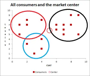
Clustering is an exploratory data analysis technique which groups data together by similarity (unnsupervised classification).
Dimensionality reduction


Dimensionality reduction is another unsupervised learning field. To prevent against the computation of huge amounts of data which results in performance and storage issues, unsupervised dimensionality reduction preprocesses data to remove noise and retain relevant information.


Thursday, June 15, 2017

Django + Js : display counting timedelta in view

Suppose you have an entry in DB with a timestamp 'start_date'. You want to display the time elapsed since 'start_date' in your view and you want that delay to grow in real time like a clock. In the following example, the user can select one entry at a time and the counter has to be updated accordingly.

Note: To achieve this it is important to work with UTC timestamps in both DB and your view

Here is what my code in django views.py looks like:

def get_entry_info(request):
    """
    Recover information for the specified entry name
    """
    entry_name = request.POST.get("name", None)
    if request.method == "POST" and entry_name is not None:
        data = {}
        # Get entry object 
        entry = MyEntries.objects.get(name=entry_name)
        data['start_date'] = int(time.mktime(entry.start_date.replace(tzinfo=None).timetuple())) * 1000 
        return JsonResponse(data)
    else:
        return HttpResponse("Invalid entry name")

Here is what my javascript code looks like:
var startDate;

// Loads content into the information panel
// @param data : data to be displayed in the information panel
function reloadInformationPanel(entryname){
    // Get job information from server
    $.ajax({
        headers: { "X-CSRFToken": '{{ csrf_token }}' },
        url: "{% url 'get_entry_info' %}",
        method: 'POST', 
        dataType: 'json',
        data: {
            'name': entryname, // outgoing data
        },
        success: function (data) {        
            startDate = new Date(data.start_date);
            startTime();
        },
        error: function(xhr,errmsg,err) {
            console.log(xhr.status + ": " + xhr.responseText); 
        }
        });
}

// Starts timer of job duration
function startTime() {
   var now = convertDateToUTC(new Date());
   var delay = new Date(now - startDate);
   document.getElementById('entry_duration').innerHTML = delay.getUTCHours() + "h" + delay.getUTCMinutes() + "m" + delay.getUTCSeconds() + "s";
   var t = setTimeout(startTime, 500);
}

// Converts a Date object to UTC
function convertDateToUTC(date) { 
   return new Date(date.getUTCFullYear(), date.getUTCMonth(), date.getUTCDate(), date.getUTCHours(), date.getUTCMinutes(), date.getUTCSeconds()); 
}

Now simply map reloadInformationPanel to the entry selection button ;)

Thursday, April 27, 2017

What is AJAX ?

AJAX = Asynchronous Javascript And Xml

Ajax is not a tehnology by itself but rather a combination of existing technologies (HTML/CSS/DOM/Javascript/XML/JSON).

What is it intended for ?


Ajax is typically used to refresh data on a web page without having to reload the entire page (e.g. asynchronously). It involves a web browser sending HTTP requests (GET/POST)  to server and processing the response to finally manipulate the page DOM (e.g. HTML tags). The user's view is thereby dynamically updated.


As you can see, Ajax requests are executed by Javascript code and the response is also handled in Javascript. The orange part stands on client's side (the web browser).

What if the format of data ?


Originally, it was XML but nowadays, JSON is preferred (JavaScript Object Notation).


Example of ajax requests


jQuery

<script>
...
$.ajax({
        headers: { "X-CSRFToken": getCookie("csrftoken") },
        url: "myurl",
        method: 'POST', // or another (GET), whatever you need
        data: {
            'mydata': 'value', // outgoing data
        },
        
        success: function (data) {        
            // success callback
            // you can process data returned by server here
        }
        });
...
</script> 

Pure javascript

<script type="text/javascript">
function ajaxFunction()
{
var xmlhttp;
if (window.XMLHttpRequest)
  {
  // code for IE7+, Firefox, Chrome, Opera, Safari
  xmlhttp=new XMLHttpRequest();
  }
else if (window.ActiveXObject)
  {
  // code for IE6, IE5
  xmlhttp=new ActiveXObject("Microsoft.XMLHTTP");
  }
else
  {
  alert("Your browser does not support XMLHTTP!");
  }
xmlhttp.onreadystatechange=function()
{
if(xmlhttp.readyState==4)
  {
  document.myForm.time.value=xmlhttp.responseText;
  }
}
xmlhttp.open("GET","time.asp",true);
xmlhttp.send(null);
}
</script>

Monday, April 10, 2017

What is inside a WCE7 BSP

The BSP (Board Support Package) is the layer that will interface the Operating System with the hardware.

It consists of the following items:
  • [Optional] Bootloader
  • OAL (OEM Abstraction layer)
  • KITL to debug the OS in development phase
  • Configuration files that specifies the board (Ex: config.bib for memory settings)
The BSP image is specific to the OS version and to the target hardware architecture.


Bootloader

When powered up, the microprocessor starts executing instructions from a specified memory address located in ROM. This code can contain the entire system for small footprint applications and will run until shutdown.
With WCE7, the system image (nk.bin) needs to be loaded to RAM from a storage disk or network because it can't fit into a ROM memory. In this case, these are the typical steps of a bootloader:
  • Minimal Initialization of the system (memory and com drivers)
  • Loads the OS image to RAM
  • Jumps to OS start address in RAM and calls startup fuction
  • The OAL takes over
Windows CE 7 includes a configurable and reusable bootloader named CE Boot with the following features:
  • Can load files from disks (IDE, PCI)
  • Emulates a console to allow user interraction at boot
  • Network support: DHCP, TFTP, IP


XLDR

In some cases, the system can be loaded in two steps : a first bootloader loads a second bootloader to RAM. The second bootloader loads the system image to RAM et jumps to it. This is necessary when:
  • The initial startup program is too small
  • The startup program on the target system is general purpose
  • The CPU has a small amount of RAM to load an image immediately and shall initialize an external RAM to host the system
XLDR is a lightweight loader that can load CE Boot in two stages.


OAL

The OAL allows the kernel to access the hardware layer (interrupts, timers, cache, IOCTL...) through an abstract interface.
When it takes over the boot phase, it accomplishes the following steps:
  • Initialize the CPU state, hardware and kernel's global variables
  • Jumps to the entry point of the kernel
  • The kernel exchanges global pointers with the OAL. From this point on, the kernel has access to all functions and variables defined in OEMGLOBAL and OAL has access to all functions and variables defined in NKGLOBAL
  • On kernel call, the OAL initializes the debug serial port (OEMInitSerialDebug) (like the bootloader did before without the help of the OAL)
  • On kernel call, the OAL initializes the rest of hardware interfaces on the device (OEMInit())
  • [Optional] On kernel call, KITL initialization (OEMKitlInit)
  • The kernel starts executing its first thread


Configuration files

File Description
config.bib Memory structure definition file
platform.bib BSP global settings. Selects which files need to included in the image depending on user-selected options/items
platform.dat Not used
platform.db Not used
platform.reg BSP global registry settings. Selects which keys to write in the registry depending on user-selected options/items
sources.cmn Starting point of the BSP build process. On top of source tree. Defines include directories and linked libraries
<MyBSP>.bat Project-specific environment variables to use in the build process. In particular, specifies the devices to include in the build.

To have a deeper look at the BSP's file structure, check the Build process.

Friday, April 7, 2017

WCE : Build process

Build process


BSP top Folder

BSP Folder Description
CATALOG BSP's catalog file (.pbcxml)
CESYSGEN BSP's makefile
FILES Files to be copied to the final image (nk.bin). Here are the main BSP configuration files. See What is a BSP ?
SRC Files needed to build the BSP

BSP SRC Folder

BSP Folder Description
INC BSP global header files
BOOT Bootloader's build directory
BOOTLOADER Networked bootloader's build directory
COMMON Code that is common to all components of the BSP
DRIVERS Target board's specific drivers
KITL KITL build directory
OAL OAL build directory

Build sequence

The build consists of 4 phases.
Phase Type Description
1 Compile phase Source and resource files are compiled into binaries. You should never need to recompile Windows CE sources.
2 Sysgen phase According to catalog items and dependenciy trees, SYSGEN variables are set. These variables act then as filters in header files to build a specific BSP.
3 Release copy phase The OS run-time files are copied to release directory.
4 Make run time image phase project.bib and project.reg are copied to release directory and according to their settings, the final run-time image is generated. Configuration files are merged: for instance, registry configuration file are merged into reginit.ini before being compiled in the final registry file.
The following diagram gives an overview of the build tools and how they interact with each other.


Behind the scene, Platform Builder relies on a set of batch scripts to compile the code. Build action calls buildemo.bat which in turn calls cebuild.bat, buildrel.bat and finally makeimage.exe.

WCE7 : Clone existing BSP

Platform Builder offers a wizard to clone an existing BSP. By doing so, we ensure that the original BSP won't be modified and we can tweak the new one for our needs. The menu is accessible from VS2008->Tools->Platform Builder->Clone BSP:

Note: If your source BSP is not in the list, ensure that a folder with its name is located in C:\WINCE700\platform.
Fill the rest of the information and click OK.


On the next window, the catalog items of your BSP will appear. You will be free to Add or Remove items:


Each item is linked to configuration variables that will be used to configure the build of the operating system. If you open the properties of any item, you should see variables like SYSGEN_xxx or BSP_xxx.

Windows CE 7 Architecture

Windows CE5 was based on a microkernel architecture.


In this type of architecture, the device drivers run in user mode which means that I/O handling routines are embedded into user-mode applications. It also means that the synchronization between the processes that share driver access needs to be done at application level, which is tricky.
NK.exe is the most privileged process of the operating system. It can access kernel memory addresses and make kernel calls.
Since Windows CE6, the architecture moved to a monolithic kernel architecture.


With this architecture, drivers and services have been moved to kernel space as dlls. NK.exe is still the most privileged process but this new architecture, by breaking the inter-process communication lines, enhances performances globally.
Component Description
GWES.dll Graphic, Windowing and Events Subsystem. It loads device drivers and manages their interface while loaded.
DEVMGR.dll Device Manager. It loads stream interface device drivers and manages their interface while loaded.
I/O Resource Manager Part of Device Manager that enumerates the available resources from registry
FILESYS.dll & FSDMGR.dll File system manager and file system driver manager.
Networking Dlls Network functionality (HTTP, TCP/IP, FTP...)
UDEVICE.exe User mode process that runs device drivers in user-mode
OAL OEM Abstraction Layer. Gives to the kernel an access to OEM hardware and maps interrupts with logical IDs
COREDLL.dll OS API (semaphore, thread, mutex, critical section...)
K.COREDLL.dll Kernel version of CoreDll (kernel device drivers links against this one)

Device driver: User mode vs Kernel mode

From performance point of view, it is better to embbed a driver in kernel space.
From security point of view, a bug in the driver might jeopardize the whole system.
For robustness, udevice.exe provides installable device driver feature, thus protecting the kernel.

Interrupt management


Component
Description
Kernel Interrupt Service Handler Can handle up to 64 separate hardware IRQS sources. It determines interrupt priority level and calls an ISR hooked to it and then sets event that is associated with interrupt ID (SYSINTR ID)
Interrupt Service Routines (ISRs) Hooked to IRQ in kernel mode. Acknowledges hardware and determines interrupt ID
Interrupt Service Threads (ISTs) Device-specific servicing for the specified Interrupt ID. Must signal completion of processing to hardware.
1. A device raises a registered interrupt.
2. The kernel catches the interrupt and calls the related Interrupt Service Routine (ISR).
3. ISR handles the interrupt and exits as quick as possible.
4. IST in driver is signaled to process the interrupt.
5. IST completes processing.

 
biz.